How to Design, Prototype, and Manufacture Electronics Hardware
Building custom hardware and electronics is easier and more accessible than ever. We show you how to get your custom designs manufactured in just a few days for under $10.

Several years ago, I embarked on a project to build an IoT sensor platform that would transmit data to the cloud in real-time. It started with an idea, and two years later, it became a real working device manufactured at scale.
Building custom hardware with electronics is easier and more accessible than ever. This post provides an overview of how to build your own electronic hardware, with pointers to software, and vendors that worked well for us. We will show you how to get your custom designs manufactured in 3 days for just a few dollars. By the end of this post, you will be familiar with the steps involved in PCB design and production. We will also discuss considerations for transitioning to mass production.
Iterative design, or agile hardware
If possible, it is always better to build a prototype using off-the-shelf components first. For instance, our product's initial prototype used a mini x86 PC, followed by an embedded ARM system running Linux, and the final product had no operating system, just an SoC running our code on bare hardware.
By iteratively designing hardware, we were able to explore several concepts and decouple software and cloud development from hardware design.
Interim prototypes also helped us get the product to customers' hands for testings, leading to valuable feedback that eventually influenced the design choices in the final product. Iterate. Strive to shed complexity with each pass.
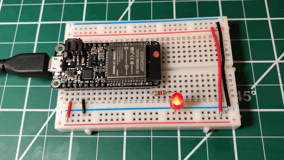
Electronics design usually always starts with a breadboard connecting several components together, then gets transferred to a PCB design that can then be printed and components placed. This step is great for dialing in your design and firmware before laying out the PCB.
Selecting components
The whole advantage of building your hardware is that you can pick the components best fitting an application, and package them in a unique form factor. Typical components present on every board is a power supply, a microcontroller, and provisions for interfacing with inputs such as sensors and outputs such as LED status lights.
Microcontroller
Devices that perform onboard computation generally use a microcontroller to process data. On the hobby side, a common microcontroller is the ATmega328P used in Arduino devices on the lower end, and a more expansive System on Chip (SoC) such as ESP32 with WiFi and multiple cores on the higher end.
Mass-produced embedded devices commonly use a variation of the STM32 processor from STMicroelectronics. It is an ARM architecture chip that includes onboard memory and capabilities to communicate with external devices. It comes in a range of models differing in speed, power consumption, and memory.
Microcontrollers do not have an operating system in a traditional sense. They simply execute your code in a continuous event loop. This provides reliably consistent processing performance (since there is no multitasking) that is key for signal processing and tackling tasks in real-time. When a device is started, the event loop starts where your core logic will execute ad-infinitum.
A microcontroller will often include ADC (analog to digital) and DAC (digital to analog) for interfacing with sensors or generating an analog signal (such as sound.) It will also have SPI and I2C bus interfaces to digitally communicate with other, specialized chips.
Most microcontrollers come in a development kit variant – a packaging to help you test your device on a breadboard, such as the ESP32 unit above.
Components
For simple projects, a quick way to find and prototype components is to use a ready-made board designed for the Arduino or Raspberry Pi. They can be found on Amazon or from places like adafruit. The added benefit is that they will often include a ready-to-use driver and a schematic.
In our case, we needed to find a high-precision ADC converter – far beyond what any microcontroller can handle by itself. We went through several chips before arriving at AD7124 from Analog Devices based on its bandwidth and low noise floor. We interfaced it with the ESP32 via an SPI interface.
Sites like Digikey and Mouser offer convenient filtering tools to narrow down your search.

A product data sheet is a trove of vital information. It will define performance characteristics and interface nuances. Be ready to read and understand every last word. For some components, this will be the only source of help.
Once a few candidates have been shortlisted, the next step is to test. A quick way to do this is with evaluation boards. Most part manufacturers offer these. They encapsulate the chip with everything it needs to run (such as power and IO interfaces) and provides simple software to test its performance.

We set up a test environment where we could plug in evaluation ADC boards to a signal generator and capture results in a consistent, repeatable way. We evaluated a few candidates until we found a chip that matched our desired performance.
Laying out your PCB
Now that you picked the components, breadboarded your circuit, it is time to design the PCB. There are two steps here: designing the schematic and laying out the actual PCB. There are several tools to accomplish this; some are proprietary such as Altium or Autodesk EAGLE, others open source like KiCad, yet others are vertically integrated with the PCB manufacturer like EasyEDA.
After evaluating a few packages, we settled on EasyEDA as it is feature-rich, free, web-based, and, made producing prototypes easy.
One thing to keep in mind is that most design tools have a finite library of components. This is because the software must know the footprint of each piece. Specialized or new parts will likely be missing. Fortunately, Digikey and Mouser will let you download models that can be imported into the design software. Search engines such as SnapEDA let you find community-made models.

Components come in 2 flavors, Surface Mount (SMT) or through-hole. The latter is more common in older devices such as radios and can be easily hand soldered. SMT components are designed to be placed by a machine for mass production, and therefore are harder to do by hand.
You may want to make the first iteration of your board through-whole, and then convert it to SMT. You should be prepared to make adjustments with early versions. Include test points so you can validate individual modules of your PCB. This will greatly simplify troubleshooting. You can also add jumpers to bypass sections.

Find a testing methodology that lets you save the results of each revision, so you will quantifiably track progress. Don't forget to include a version number on the board for easy reference.
Producing boards
We live in genuinely amazing times when a PCB can go from being on screen to being in your hands within a few days. Multiple services will let you submit a design on Friday and deliver a ready-to-use board the following Wednesday. You can use a tool like PCBShopper to find PCB manufacturers.
Since we used EasyEDA, we relied on JLCPCB exclusively for PCB printing and assembly with great results. Our PCB designs would typically arrive from China within 3 days of placing an order, with slightly longer lead times when we chose to have them place the SMT components.
Assembly
Populating a PCB with components, especially at low volumes, used to be a tedious process involving hand soldering or using a reflow oven.
Many PCB printing services now offer automated SMT assembly for a few bucks (provided the components are available in their stock.) In the case of JLCPCB, not all parts are available for automated SMT assembly, so your results can vary.

If you have to manually place a component during testing, consider using a larger version in the pre-production board to make it easier to assemble. Reduce manual assembly as much as possible as it is a potential source for defects.
For more complex endeavors, local PCB assembly shops can handle more complex manufacturing that involves multiple suppliers.
Design for manufacturing
An essential consideration for building things at scale is logistics. Having to wait for parts to arrive from different suppliers or using parts with limited availability can introduce significant delays.
When designing your PCB and picking components:
- Minimize the number of suppliers.
- Avoid components that are nearing their End-of-Life.
- Make sure the components are available where the final assembly is performed (some parts from Mouser or Digikey are not available in Asia).
- Use surface mount components (SMT) as a through-hole assembly is more labor-intensive.
- Be mindful of manufacturing tolerances. Pick and place machines are not always perfect; leave enough space between components.
Conclusion
Building and manufacturing electronics is easier and more accessible than ever before. Even low volume manufacturing of custom electronics is now cost-effective. With cheap edge compute power readily available, there are endless possibilities for new devices to perform previously impossible things. What will you build?
--
Please leave a comment below and thanks for reading!